
The basic patterns of drill holes employed in opencast mines are :-
- Square Pattern
- Staggered (or) Triangular pattern
- Single row blasting pattern
- Multi blasting pattern
- Wedge cut pattern
- Diagonal blasting pattern
• Square Pattern:
- This pattern can also be called as multi row pattern.
- The drill holes are drilled in rows, one behind the other.
 |
| square pattern |
• Staggered (or) Triangular pattern:
- The drill holes are drilled in rows.
- The second row holes are positioned midway between the first row of holes.
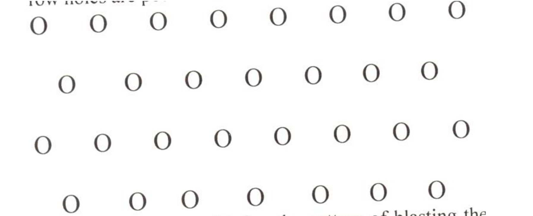 |
staggered or triangular pattern |
However considering the pattern of blasting the patterns can be classified as follows:
- Single row blasting pattern.
- Multi row blasting pattern.
- Wedge blasting pattern.
- Diagonal blasting pattern.
Single row blasting pattern:-
- The holes are drilled in a single row. The specific explosive consumption is low.
- The danger associated with fly rock is more.
.jpeg) |
Multi blasting pattern:-
- The holes are drilled in several rows.
- The holes may be staggered or square.
After the holes are drilled, blasting may be carried out either by Wedge cut pattern or Diagonal blasting pattern
Wedge cut pattern:-
- This pattern as shown in the fig, is adopted in hard and medium hard rocks.
- The delays are fixed from the middle to the ends as shown in the fig.
.jpeg)
The center blast hole in the first row blasts first, followed by the blast holes connected to the
second holes (from the center) with delay No.1,and then in the sequential order of the delays.
Diagonal blasting pattern:-
- This type of blasting pattern is carried out in benches where the cleavage plane of the rock is parallel to length of the face.
- This pattern reduces secondary blasting.
- The blast holes can be drilled in square or staggered pattern.
- The delays must be planned in such a way that the blasting proceeds from one side to the other.
- It must be ensured that the delays are in proper sequence to avoid any cut off.
 |
| diagonal blasting pattern |
- The quantity of explosive required per round of holes is an estimate only since it is a general
- practice to go by Trial and error method.
- This is because of the variation in the physiological properties of the rock mass.
- However, the quantity of charge, Q, can be calculated by the formula
- Q= E (H – St) D2 /4 ,
- where
- H= Depth of the hole,
- St= Height of the stemming column,
- D= Diameter of the hole,
- E= Specific weight of the explosives.
- Specific consumption (C ) of the explosive= Q / BSH Kg/m3
- Where, B=Burden,
- S=Spacing and
- H=height of the charge.
- Powder factor P =B S H / Q m3/Kg.
- The charge required per hole is first calculated
- considering the blast geometry and the powder factor.
- Then the total charge required can be easily calculated.
Deck charging
- Deck charging is one of the controlled techniques adopted to distribute the blasting energy to the entire length of the drill hole.
- This method is followed in benches with varying strata and Grade.
- The primer charge is given at the bottom of the hole followed by base charge.
- Then a part of the hole is filled with stemming material and the same procedure is repeated as shown the second fig.
Air deck method
.jpeg)
Multi deck in hole delay method
.jpeg) |
| multi deck in hole delay method |
- Deck charging will result in less oversize boulders and will have smaller uncontrolled zone of rock breaking .
- Generally in the lower part of the hole 2/3 rd of the charge is placed and the remaining 1/3 rd of the explosive is distributed in the upper two decks.
- The explosive in the upper decks is generally of lower strength compared to that of the bottom charge.
- The charges at each of the decks are primed separately.
- Dec charging with air gaps is a modified technique.
- In this type of charging air gaps are introduced at places where stemming is required with the help of expanding type air bags.
- The No. of decks and the length of the stemming column /air gap depends upon the nature of rock strata.
- The length of the air gaps generally varies from 20 to 35% the length of the hole.


.jpeg)
0 Comments